Reverse Osmosis System Installation Diagram
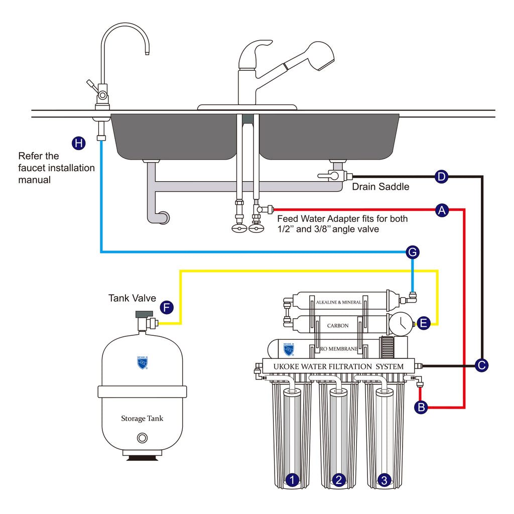
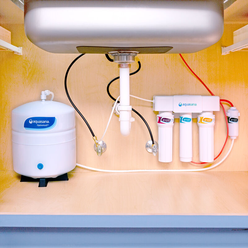
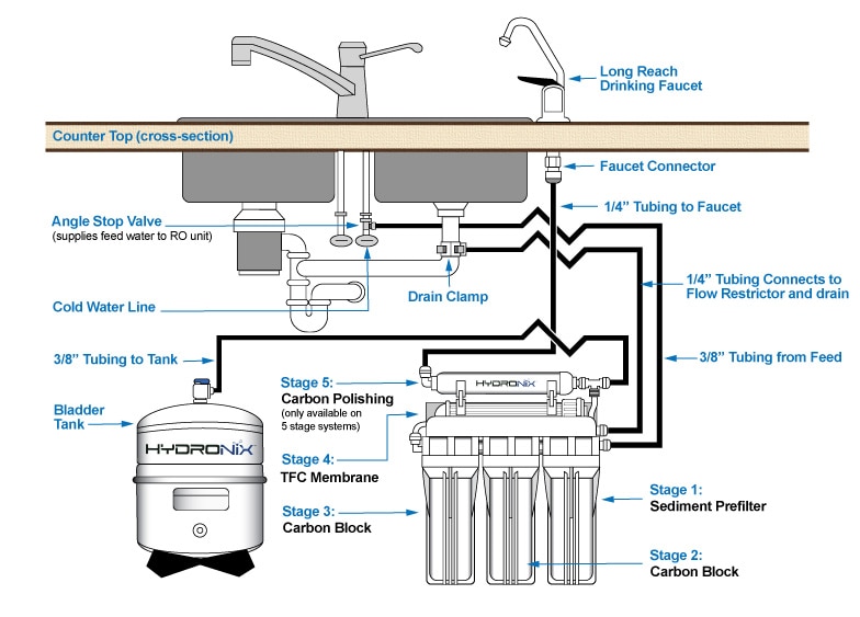
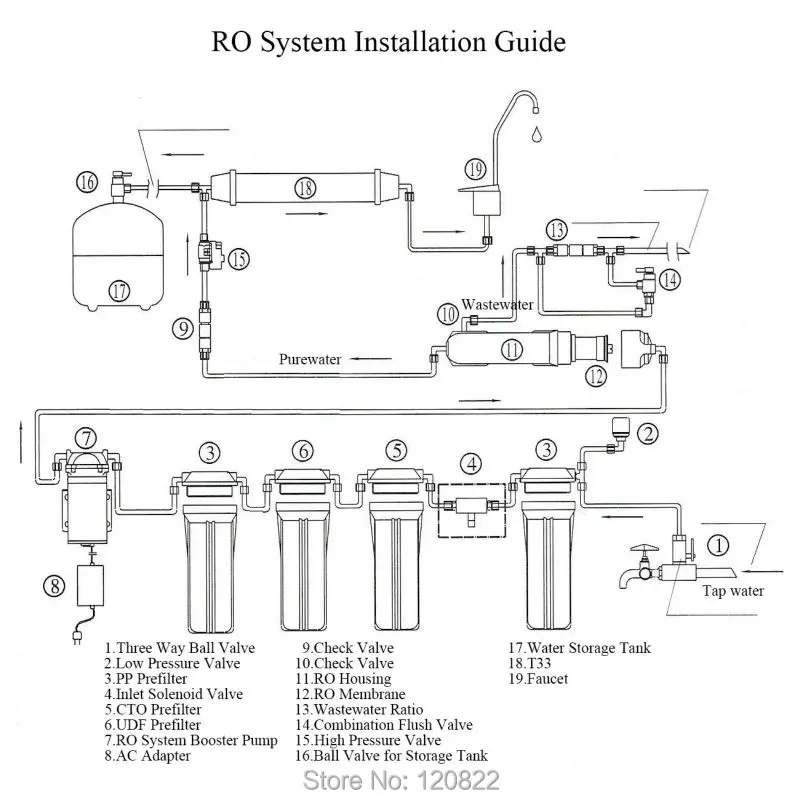
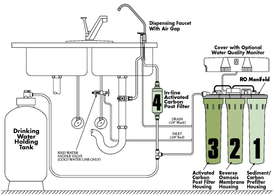
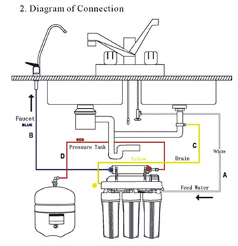
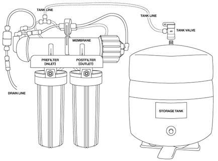
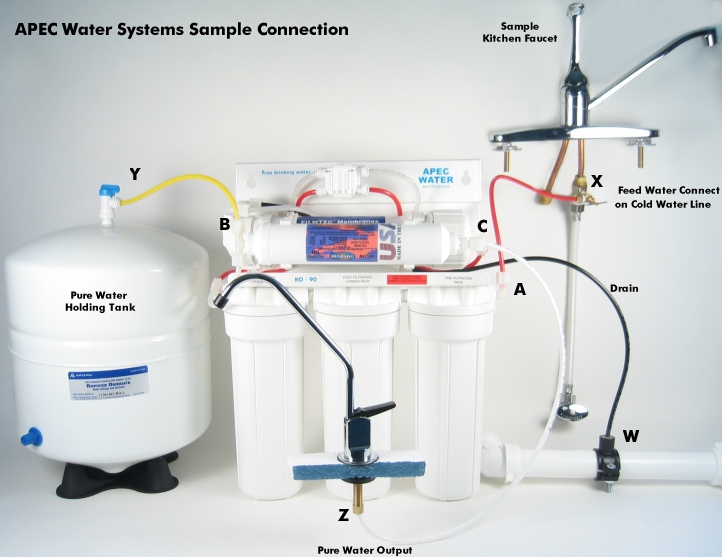
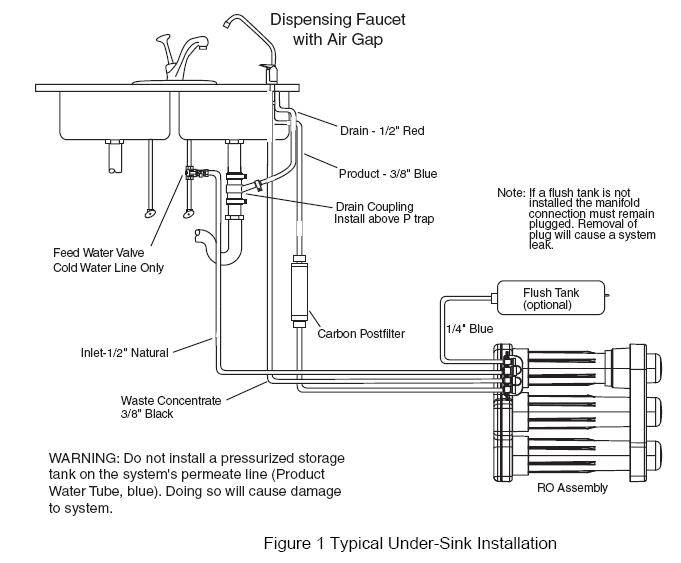
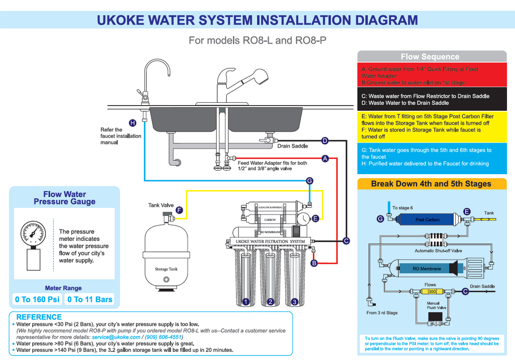
Reverse osmosis system installation diagram. Filter rack is connected to cold water supply with feed water adapter 4 and feed valve 5. Installing the Water Storage Tank. 2 Where to Install an RO System.
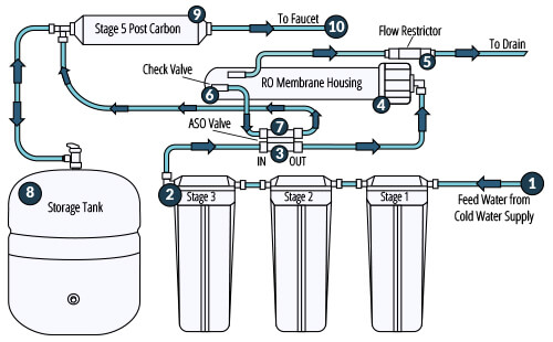
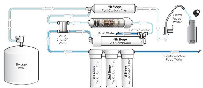
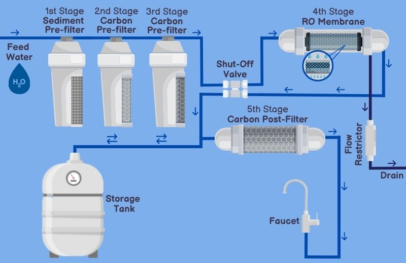
Recovery Product Water Flow Rate Feed Water Flow Rate x 100 Example. Sediment Prefilter - Water travels from the source through the Sediment Prefilter. Installation Diagram of 4 Stage Reverse Osmosis Systems The 3 stage 4 stage and 5 stage reverse osmosis systems install exactly the same.
Its free to sign up and bid on jobs. The Express Water Reverse Osmosis System is designed to provide you with years of great tasting pure drinking water and trouble-free service. The permeate is the final and desired product of reverse osmosis filtration.
Reverse osmosis system is a five-stage filtration unit functioning as follows see section 24 for. This post is the ultimate guide to installing a reverse osmosis system by yourself with clear diagrams and a step-by-step trouble-free way of how you can set up your RO system. THE REVERSE OSMOSIS SYSTEM SHOULD BE INSTALLED INDOORS AND IT IS SUGGESTED THAT IT NOT BE IN DIRECT SUNLIGHT OR EXTREME COLD.
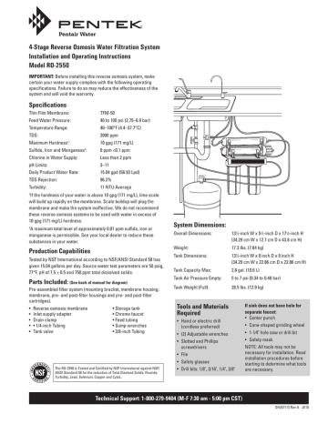
The system prior to leaving site andor before use. The minimum water pressure should be at least 30 psi. The system s minimum operating pressure.
Connect the 38 or 14 tube fitting to an incoming water source. To calculate recovery use the following formula. Installing the Drain Saddle.
3 How to Install a Reverse Osmosis System. Reverse Osmosis can reduce up to 99 of contaminants.
Installation Diagram of 4 Stage Reverse Osmosis Systems The 3 stage 4 stage and 5 stage reverse osmosis systems install exactly the same.
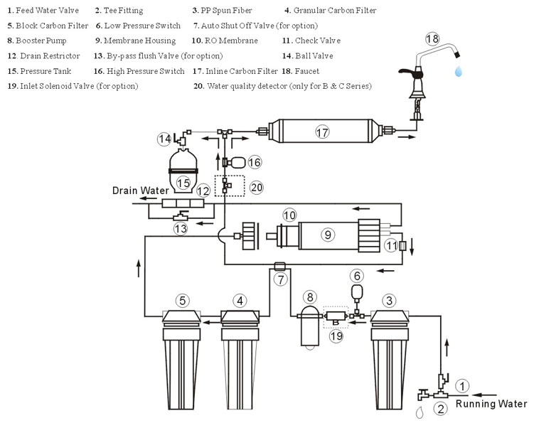
Depending on the weave of the membrane only a certain percentage of contaminants can pass through. AT-Series reverse osmosis systems are designed to reject up to 985 NaCl unless computer projections have been provided or stated otherwise. Reverse Osmosis Diagram September 16 2021 April 25 2021 by admin Here you will find the detailed reverse osmosis diagrams include a complete RO system diagram and its components. Click on the PDF emblem and you will be transferred to the diagram. The system s minimum operating pressure. To calculate recovery use the following formula. Push in collet squarely against face of fitting. Water is pushed up against this membrane at pressure. Search for jobs related to Reverse osmosis system installation diagram or hire on the worlds largest freelancing marketplace with 20m jobs.
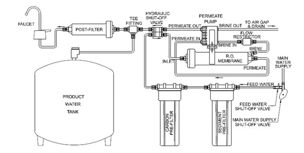
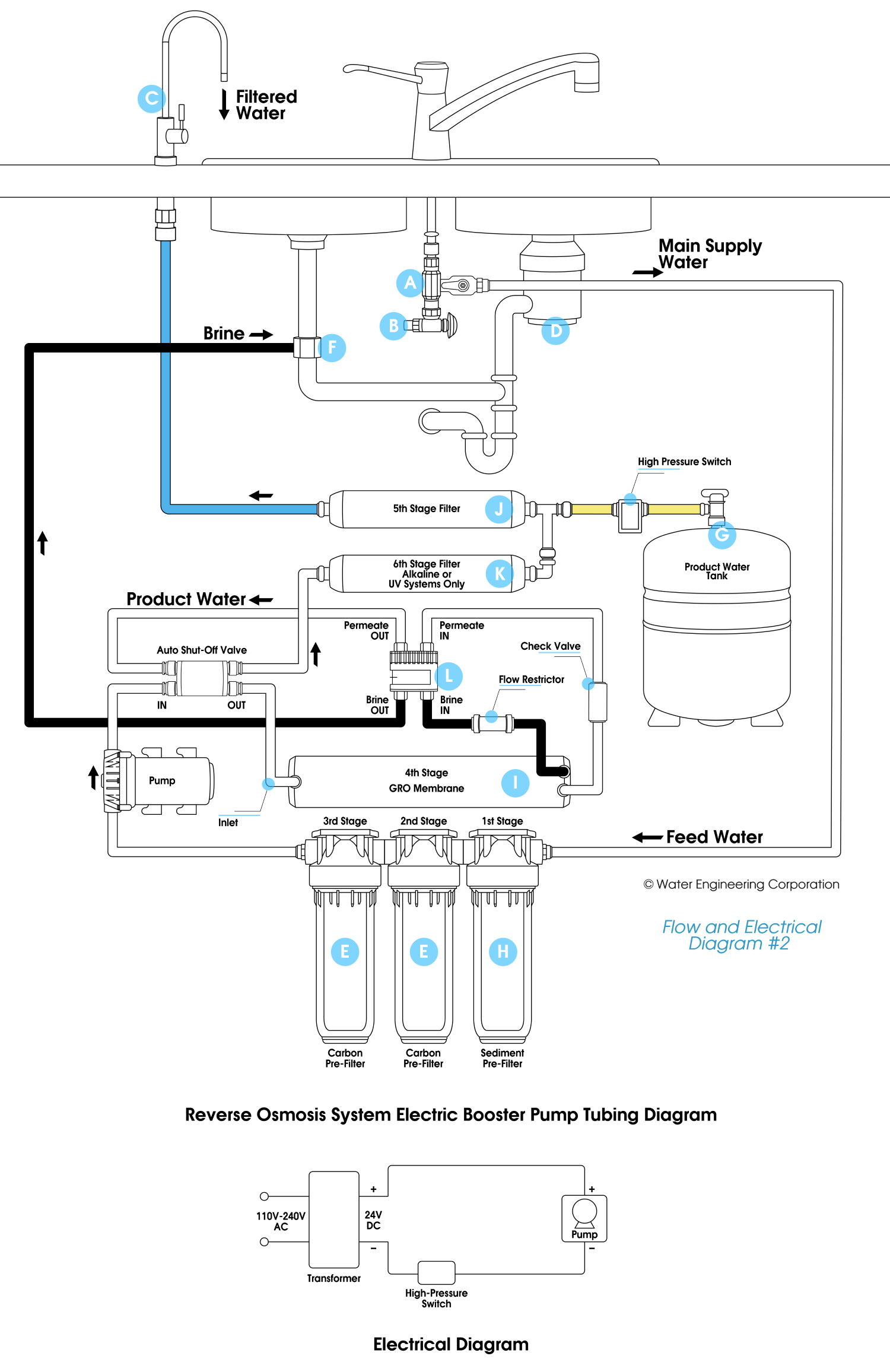
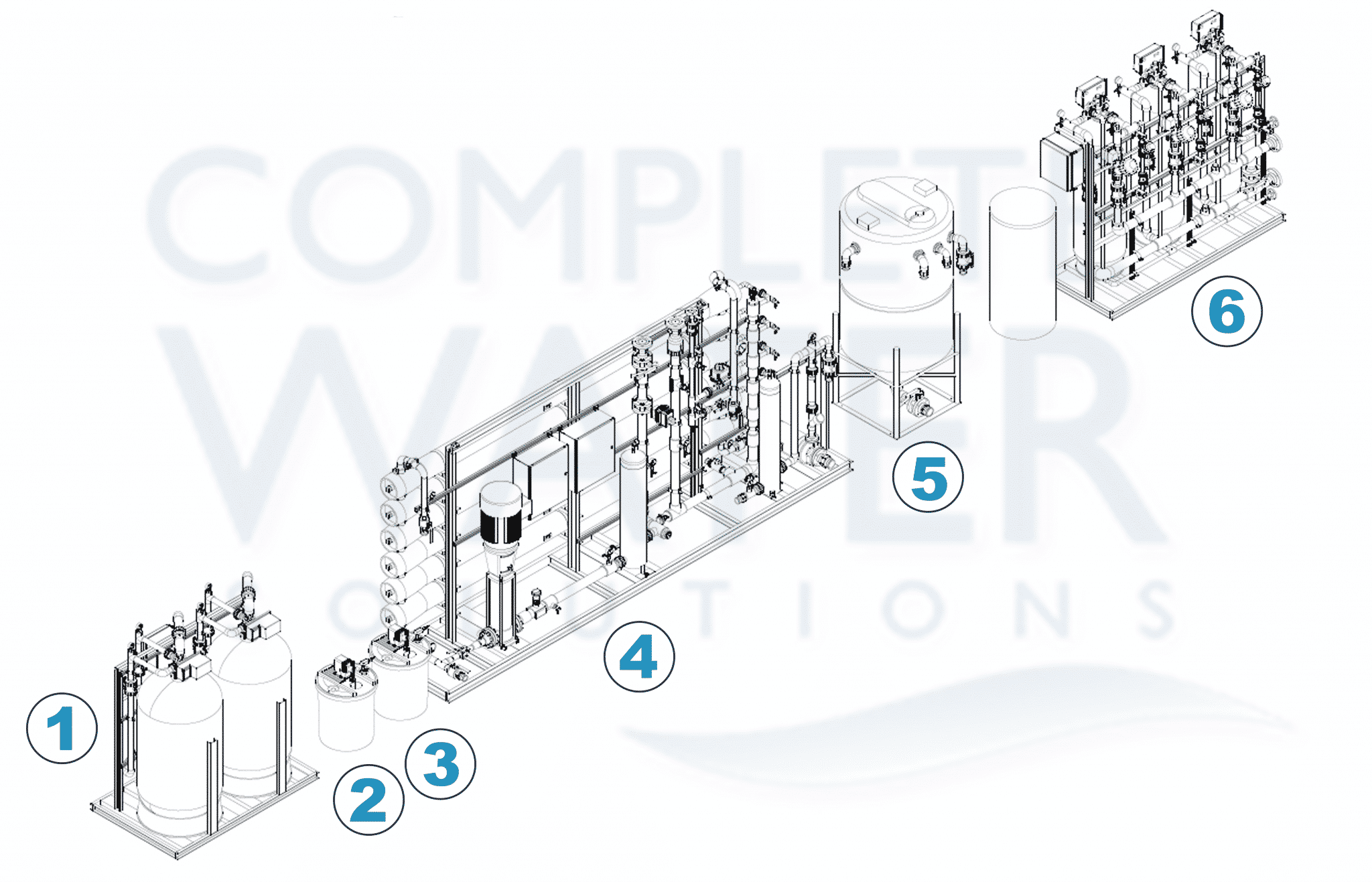
With the collet held in this position the tube can be removed. Your new Reverse Osmosis Drinking Water System uses a combination of filtration technologies to reduce unwanted contaminants in your water supply. THE REVERSE OSMOSIS SYSTEM SHOULD BE INSTALLED INDOORS AND IT IS SUGGESTED THAT IT NOT BE IN DIRECT SUNLIGHT OR EXTREME COLD. The system s minimum operating pressure. The permeate water is sometimes referred to as pure water or simply product water and usually has 95-99 of the dissolved salts removed from it. Diagram of a 4 stage Reverse Osmosis system with Booster Pump and Permeate Pump. Industrial Reverse Osmosis RO Systems Diagram Engineered in USA by Pure Aqua Inc.














Post a Comment for "Reverse Osmosis System Installation Diagram"